Can a Bad Stator Cause Backfire? Understanding the Electrical–Ignition Link
Short answer. Yes, indirectly. A failing stator can set off a chain reaction that leads to weak or mistimed ignition, unburnt fuel in the exhaust, and backfire. That’s not the only cause of backfire, yet the charging and ignition systems often sit at the root of the problem.
If you design, buy, or maintain engines and rotating machinery, you already know how tightly electrical integrity and combustion stability are coupled. In this guide we’ll connect the dots. We’ll show how stator failure symptoms map to backfire behavior, then step up a level to the motor lamination fundamentals that drive stator reliability in the first place. The goal is practical: give you the physics, the tests, the material and manufacturing trade-offs, and the next steps to make better engineering and procurement decisions.
In other words, we’ll go Problem → Explain → Guide → Empower.
In This Article
- What Does a Stator Do? The Heart of Your Electrical System
- The Indirect Connection: How a Failing Stator Leads to Backfire
- Common Symptoms of a Bad Stator
- Other Common Causes of Engine Backfire (Differential Diagnosis)
- Diagnosing a Bad Stator
- Engineering Fundamentals: Why Laminations Matter to Stator Reliability
- Guide: Material and Manufacturing Choices That Reduce Electrical–Ignition Problems
- Which Application Is This For? Best-Fit Recommendations
- Preventing Stator-Related Backfires and Other Issues
- Case Examples and Data Insights
- Your Engineering Takeaway
What Does a Stator Do? The Heart of Your Electrical System
Backfire is a combustion symptom. A stator sits upstream in the electrical supply chain. It’s the stationary part of a generator or alternator that converts mechanical motion into electrical power. That power keeps the battery charged and feeds the ignition system, the ECU/ECM, sensors, fuel injectors, lights, and every other electrical load.
Power Generation: How the stator creates AC voltage
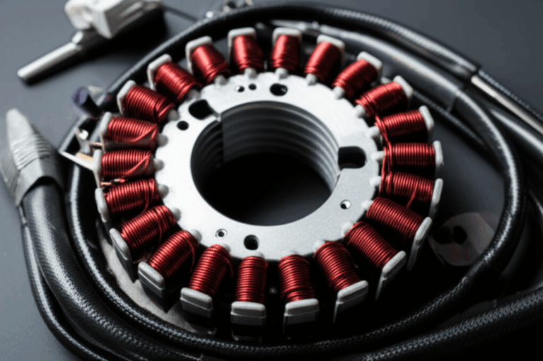
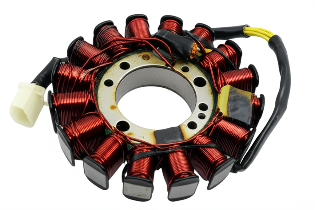
A rotor or flywheel spins past the stator’s laminated iron core and copper windings. Changing magnetic flux induces an AC voltage in those windings. If you’re dealing with a permanent magnet alternator on a motorcycle, ATV, or small engine, the magnets live on the flywheel and the stator sits fixed around it. In an automotive alternator the rotor produces a controlled magnetic field through slip rings while the stator generates AC.
Under the hood, lamination stacks limit eddy currents. They do the same job baffles do in a tank that sloshes. Without laminations, eddy currents flow freely like big whirlpools that waste energy as heat. Laminations break those whirlpools into small, low-energy ripples. That keeps the stator cooler and more efficient.
If you evaluate stator core design or procurement, the geometry and quality of the stator core lamination affect flux density, loss, and thermal headroom. That headroom can be the difference between robust operation and a marginal charging system that sags under load.
Role in Charging and Ignition: Converting AC to DC
Raw AC from the stator passes through a rectifier/regulator. The rectifier diodes convert AC to DC. The regulator holds voltage within spec to protect the battery, ECU, fuel injectors, ignition coils, and sensors. In carbureted engines the ignition still depends on a strong spark at the right time. In fuel-injected engines the ECU needs clean power to time spark and meter fuel correctly.
When voltage drops, components limp. Ignition energy falls. Injectors pulse inconsistently. Sensors drift. The result can be misfire. Unburnt fuel ends up in the exhaust, then ignites there. That’s backfire.
The Indirect Connection: How a Failing Stator Leads to Backfire
A bad stator does not directly light fuel in the exhaust. It weakens or scrambles the electrical inputs that allow clean combustion.
Weak or intermittent spark production
- Low stator output creates low system voltage.
- Ignition coils saturate poorly which yields a weak spark at the spark plugs.
- That weak spark causes incomplete combustion or outright misfire.
- Unburnt fuel passes into the exhaust where it can ignite as an afterfire.
You might hear “backfire through the exhaust” on deceleration or during throttle blips. You might also see “backfire through the carburetor” on some carbureted engines if the mixture ignites in the intake. Both stem from misfire and timing problems that low voltage can aggravate.
Battery drain and low system voltage
- A failing stator cannot keep the battery charged.
- Voltage sags stress the ECU/ECM, ignition coils, and fuel injectors.
- The ECU can log diagnostic trouble codes if it sees undervoltage. It may reset under transient dips.
- Sensors like the O2 sensor, TPS, MAP, and MAF can report erratic data when supplied voltage falls below spec. The engine can run lean or rich. Either condition can cause backfire.
- You’ll often see rough idle, engine hesitation, engine cutting out, or stalling when the charging system struggles.
Impact on engine timing, indirectly
The stator does not set ignition timing. Yet unstable voltage can cause ignition modules, crankshaft position sensors, or camshaft sensors to misread. That can shift spark timing enough to create afterfire or backfire. It can also raise cylinder temperatures which invites pre‑ignition or detonation. That is a different failure mode than backfire, yet it lives in the same neighborhood of electrical and mixture control issues.
Common Symptoms of a Bad Stator
Look for patterns, not single hints. Backfire alone could be exhaust or fueling. Backfire with charging system issues points toward the stator and rectifier/regulator.
Charging system failures
- Battery not charging or a dying battery during rides
- Dim headlights or flickering dashboard lights
- Difficulty starting or a no‑start that resolves after a charge
- Voltage that fails to rise at idle or at 2,000–3,000 RPM
- Overheating rectifier/regulator, sometimes with a burnt odor
Engine performance issues
- Weak spark backfire noises during deceleration
- Rough idle, engine hesitation, or a stumble on throttle
- Intermittent spark caused by loose grounds or stator winding faults
- Loss of power at high RPM when ignition energy demands rise
- Check engine light and stored DTCs for misfire, lean or rich mixture
- Excessive fuel consumption and emissions test failure when the ECU compensates for bad data or low voltage
Other stator failure symptoms include stator overheating, winding resistance out of spec, open circuit stator leads, and short circuit between phases or to ground. Oil contamination can appear if the design places the stator inside the engine case. Insulation breakdown often shows up there.
Other Common Causes of Engine Backfire (Differential Diagnosis)
Keep the stator on your list, not at the top by default. Backfire has many causes.
Fuel mixture problems
- Running rich pushes unburnt fuel into the exhaust. You’ll smell it.
- Running lean raises exhaust gas temperature which can ignite mixture late.
- Faulty fuel injectors, a clogged fuel filter, or a failing fuel pump can swing the mixture.
- A carburetor with blocked jets or a dirty carburetor can cause lean surge or rich burble.
- A bad fuel pressure regulator drives mixture off target.
Ignition timing issues
- Ignition firing too early or too late can pop through the intake or exhaust.
- A faulty crankshaft position sensor or camshaft position sensor can shift timing.
- A slipping timing chain or belt can also move valve timing which changes combustion phasing.
Exhaust system leaks
- A small leak at the exhaust manifold or header can pull in fresh air on decel.
- That oxygen lets unburnt fuel ignite in the exhaust. You hear sharp cracks.
Direct ignition component failure
- Bad spark plugs, fouled plugs, worn plug wires, or weak ignition coils can cause misfire.
- Always inspect plugs first. They tell a story about mixture and spark quality.
Vacuum leaks
- Cracked vacuum lines or leaking gaskets create a lean mixture, especially at idle.
- The ECU trims fuel to compensate, yet trims saturate. Misfire and backfire can follow.
Not backfire, but often confused with it
- Engine knock or detonation is abnormal combustion inside the cylinder, not in the exhaust.
- Pre‑ignition is uncontrolled ignition before the spark event. It is dangerous.
- Afterfire vs backfire: Afterfire typically refers to combustion in the exhaust on decel. Backfire often refers to an intake pop, although many use both words interchangeably.
Diagnosing a Bad Stator
You don’t need to guess. A few deliberate tests will tell you if the stator and the rectifier/regulator can carry the electrical load.
Visual inspection
- Disconnect the stator and inspect connectors for corrosion or heat damage.
- Look for burnt wires, melted insulation, or oil contamination where it doesn’t belong.
- Check ground wire integrity. Verify ground points are clean and tight.
Battery voltage test
- Fully charge the battery. Perform a battery load test if you suspect it’s weak.
- With a multimeter at the battery, measure key-off voltage. Healthy batteries sit around 12.6–12.8 V for 12 V systems.
- Start the engine. At idle, voltage should rise above resting voltage. Raise RPM. Voltage should stabilize within the regulated range, often around 13.5–14.4 V. Always check your service manual for spec.
AC output test at RPM
- Unplug the stator leads at the regulator. Measure AC voltage across stator phases.
- Test AC output at idle and at the specified RPM in the service manual.
- Most three‑phase permanent magnet alternators rise linearly with RPM. You’ll often see dozens of volts AC per phase at elevated RPM. If voltage is low or unbalanced between phases, the stator likely has a winding fault.
Stator resistance test
- With the engine off and the stator unplugged, measure resistance between each winding pair.
- Compare readings. They should match closely. Any open circuit reading indicates a break. Any very low reading can indicate a short.
- Measure resistance from each stator lead to ground. It should read open circuit. Any continuity to ground signals an insulation breakdown.
Ground test and voltage drop test
- Perform a voltage drop test on main grounds while cranking and at fast idle.
- Check for excessive drop across the main positive feed from the rectifier to the battery.
- Bad grounds create intermittent spark and sensor errors that mimic a failing stator.
Rectifier/regulator check
- Test rectifier diodes with a multimeter’s diode function.
- Verify the regulator holds voltage within spec at various loads and RPMs.
- Regulators often fail along with a bad stator. Replace both if the root cause is not clear.
Advanced tools
- An oscilloscope helps you visualize ignition coil primary voltage, injector pulse width, and crank/cam sensor waveforms. You’ll catch intermittent dropouts that a multimeter can miss.
- A scan tool reads ECU data, fuel trims, misfire counters, and DTCs. It confirms whether the ECU is fighting low system voltage or sensor faults.
Engineering Fundamentals: Why Laminations Matter to Stator Reliability
Now the bigger picture. Why do some stators handle heat and load spikes better than others? The answer starts with lamination material, thickness, and insulation quality.
- Eddy current loss: A changing magnetic field induces circulating currents in the core. Those currents waste energy as heat. Thinner, well-insulated laminations cut eddy current loops into tiny paths, which slashes loss. Think of eddy currents like small whirlpools in a river. Laminations break them apart.
- Hysteresis loss: As magnetic domains flip with each electrical cycle, the core loses energy. Lower coercivity steels reduce hysteresis. Coercivity is simply how hard it is to magnetize and demagnetize a material.
- Magnetic permeability: It measures how easily magnetic field lines pass through the core. High permeability steels deliver strong flux with less magnetizing force. Picture a sponge that soaks up water effortlessly. That’s high permeability.
These losses turn into heat. Excess heat bakes insulation. It accelerates winding varnish aging and regulator failure. It can also demagnetize rotor magnets in permanent magnet machines. That knocks charging output down and sets the stage for weak spark and backfire under load.
Material selection, coating system, and stamping quality define loss and thermal behavior. You’ll find a useful overview here: electrical steel laminations.
Guide: Material and Manufacturing Choices That Reduce Electrical–Ignition Problems
Here’s the practical tie‑in. Your choices in core material and process ripple into field reliability, charging stability, and yes, the odds of backfire due to electrical weakness.
Material considerations
- Silicon steels (M‑grades)
- Best for general‑purpose motors and alternators where cost and performance must balance.
- Up to 3.2% silicon improves resistivity which lowers eddy current loss.
- Available in thicknesses like 0.35 mm or 0.50 mm for low to mid‑frequency use.
- Pros: Good mix of loss, cost, formability. Global availability.
- Cons: Losses rise at higher frequencies. Not ideal for very high-speed BLDC spindles.
- Non‑oriented vs grain‑oriented steels
- CRNGO (cold‑rolled non‑oriented) suits rotating machinery because properties are uniform in all directions.
- CRGO (grain‑oriented) targets transformers since flux runs primarily in one direction. Use it where that directional advantage matters. Avoid it in isotropic rotating fields unless design warrants.
- Cobalt alloys and advanced grades
- Higher saturation flux density supports compact, high‑power‑density machines.
- They cost more and demand careful stamping and heat treatment.
- Consider them for aerospace or high‑speed EV traction stators where every watt of loss matters.
- Insulation coatings
- The interlaminar coating must survive punching, stacking, and operating temperature.
- Coatings define interlaminar resistance, which directly controls eddy current loss.
- Specify class, thickness, and cure schedule. Poor coatings drive hot spots and shorts.
- Lamination thickness
- Thinner laminations reduce eddy currents. They also increase piece count and stamping cost.
- Match thickness to the electrical frequency of the machine. High RPM and high electrical frequency point to thinner stock.
Manufacturing and assembly processes
- Stamping vs laser cutting vs EDM
- Stamping leads in high volume with low part cost and high repeatability. You must control burr height because burrs poke through insulation and cause shorts.
- Laser cutting shines in prototyping and low‑volume complex geometries. Watch the heat‑affected zone because it can increase local losses. Post‑process stress relief helps.
- EDM gives crisp edges and minimal HAZ. It’s slower and more expensive which suits critical prototypes.
- Stack assembly: Interlocking, bonding, welding, riveting
- Interlocking laminations work like LEGO bricks. They build strong stacks without heat input that can degrade magnetic properties.
- Bonding with specialized adhesives creates low‑vibration stacks with excellent magnetic performance. Control bondline thickness evenly.
- Welding introduces localized heat and stress that can raise loss. Use it sparingly or away from primary flux paths.
- Burr control and deburring
- Burrs create electrical bridges between laminations. That raises eddy current loss and heat.
- Set burr specs for punch quality. Verify with cross‑section inspections and stack resistance measurements.
- Core testing
- Specify Epstein or single‑sheet tester results from the steel mill.
- Validate core loss on representative stacks. Track B‑H curves and permeability across batches.
If you’re reviewing a core vendor, look at their capability across these steps. You can also scan their portfolio to understand fit for purpose: motor core laminations.
Why this matters for backfire
A cooler, lower‑loss stator that maintains output at idle and high RPM keeps system voltage healthy. Healthy voltage lets coils fire strong, injectors meter correctly, and the ECU stay online. That prevents the weak‑spark backfire cycle that starts with a marginal charging system.
Which Application Is This For? Best‑Fit Recommendations
Different platforms call for different trade‑offs. Here’s how to match materials and processes to use cases that commonly see backfire complaints.
- Motorcycles, ATVs, and small engines with permanent magnet alternators
- Use CRNGO silicon steel with tight thickness control and robust insulation coatings.
- Favor interlocked or bonded stacks to maintain mechanical integrity under vibration.
- Pay attention to thermal path and oil cooling where the stator lives in the engine case.
- Specify high‑temperature magnet wire enamel and vacuum impregnation that handles hot oil.
- If your design uses a high‑speed BLDC architecture, evaluate a purpose‑built bldc stator core with thinner laminations.
- Automotive alternators and 12 V charging systems
- Stator and rotor design must support stable output at idle because modern vehicles load the bus heavily at low RPM.
- Optimized slot geometry and low‑loss laminations reduce copper loss and heat during city driving.
- Pay equal attention to the rotor core and pole geometry. Flux path quality on both sides reduces ripple and loss. More on that here: rotor core lamination.
- High‑frequency and high‑power‑density machines
- Consider thinner laminations and low‑loss grades. Cobalt alloys become attractive when size and efficiency matter more than cost.
- Bonded stacks reduce vibration and acoustic noise which can mask misfires and spark knock during NVH testing.
- Marine and powersports
- Salt, moisture, and thermal cycling attack insulation and connectors. Specify corrosion‑resistant coatings and potting where needed.
- Add redundancy for ground returns and shielded sensor wiring. Electrical noise can corrupt crank and cam signals.
Preventing Stator‑Related Backfires and Other Issues
A few disciplined practices prevent the cascade from low output to backfire.
- Keep the battery healthy. Perform regular battery load tests and replace weak batteries before they sag under cranking and idle loads.
- Monitor charging system health. Verify regulated voltage at idle and across RPM bands during service.
- Inspect grounds and connectors. Clean and reseat grounds. Check for green copper, heat discoloration, and pin drag.
- Replace the rectifier/regulator proactively in high‑mileage powersports applications. It often fails alongside the stator.
- Use OEM‑spec or better stator assemblies with proven lamination stacks and insulation systems. Avoid bargain units with unknown steel and coating.
- Add thermal margin. Improve airflow, oil flow, or heat sinking around the stator in custom builds or high‑load duty cycles.
- Follow torque specs and routing for harnesses. Strain on connectors creates intermittent faults that look like ignition timing problems.
Case Examples and Data Insights
Let’s walk through a representative scenario that ties backfire to a failing stator through the chain of cause and effect.
- The scenario: A motorcycle rider reports backfire on deceleration and a pop during hard acceleration. Headlights dim at idle. After a week of commuting the battery dies overnight.
- Initial checks: Spark plugs show black soot which suggests rich running or weak spark. The rider charges the battery. Symptoms improve briefly then return.
- Electrical tests: Charging voltage sits at 12.4 V at idle and barely rises with RPM. AC output at the stator measures well below spec and phase-to-phase voltage is unbalanced. The rectifier/regulator case feels hot after a short ride.
- Root cause: The stator windings show a low-resistance short between phases and insulation breakdown to ground under heat. The regulator also tests out of spec.
- Outcome: Replacing the stator and regulator restores charging voltage. The ECU stops trimming rich to compensate for low voltage sensor errors. Misfire disappears. Backfire vanishes.
You’ll find similar storylines on older ATVs where mud, water, and heat cycle the charging system mercilessly. Battery drain starts the death spiral. Low voltage triggers misfires. Unburnt fuel lights in the pipe. That’s afterfire.
Broad industry data reinforces the pattern. Battery and charging failures are among the most common roadside service calls. While no public dataset carves out “stator-caused backfire” as a standalone line item, charging system faults correlate with misfire, rough running, and stalls. Those are the classic precursors to exhaust afterfire.
Your Engineering Takeaway
Here’s the short list you can take to a design review or a supplier call.
- Yes, a bad stator can cause backfire indirectly. It does so by lowering system voltage which weakens ignition energy and destabilizes the ECU and injectors.
- Diagnose before you replace parts. Do a battery load test. Measure DC bus voltage at idle and under load. Perform an AC output test on the stator. Check stator resistance and ground leakage. Verify the rectifier/regulator.
- Rule out the usual suspects too. Look for exhaust leaks, vacuum leaks, clogged fuel filters, fouled plugs, and weak coils. Confirm crank and cam sensors are clean and powered.
- Protect the stator from heat. Pick low‑loss laminations with the right thickness. Specify coatings and stack processes that resist shorts and delamination. Control burrs.
- Match material to application. Use CRNGO silicon steel for most rotating machines. Move to thinner stock or premium alloys for high‑frequency BLDC designs.
- Build quality into the stack. Choose interlocking or bonding where it helps NVH and magnetic performance. Limit weld heat in primary flux paths.
- Keep connectors and grounds pristine. Electrical gremlins hide there and they love to imitate timing faults.
If you want a quick refresher on stator stack choices and how they influence charging stability and temperature rise, start with the fundamentals here: stator core lamination. Then broaden to the ecosystem of laminations for other rotating components: motor core laminations. For deeper material selection context see electrical steel laminations. If your design needs balanced flux paths on both sides of the airgap, review the interplay with rotor core lamination.
Action items you can take this week:
- Add a charging system check to your service or end‑of‑line test plan. Include AC stator output by RPM, regulated DC voltage, and ground voltage drop.
- Request lamination loss data at your operating flux density and frequency. Confirm coating class and post‑process treatments in your drawings.
- Audit connector sealing and ground bosses on your harness and chassis. Fix any high‑resistance points.
- If you’re in procurement, ask for PPAP or similar quality documentation on stator stacks including burr measurements, stack factor, and interlaminar resistance. It pays off in field reliability.
Backfires grab attention. The fix usually starts with a meter and a calm checklist. Keep the electrical backbone healthy, and the combustion will behave.