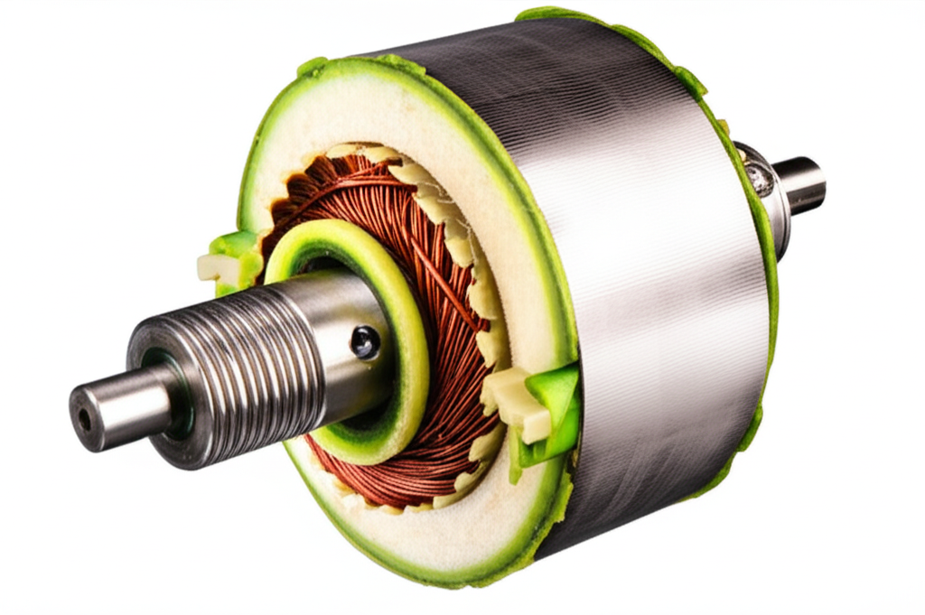
Armature vs. Stator: Are They the Same? Understanding Key Electric Machine Components
Table of Contents
- The Short Answer: No, They Are Distinct Components
- What Is an Armature?
- Definition in Plain English
- Function in Motors and Generators
- Where It Sits: Rotor or Stator
- Key Characteristics and Materials
- Everyday Examples
- What Is a Stator?
- Definition and Role
- Functions Across Different Machines
- What It’s Made Of and Why
- Common Examples You’ll Recognize
- Armature vs. Stator: Key Differences Summarized
- The Interplay: How Armature and Stator Work Together
- When an Armature Is Part of the Stator (and Vice Versa)
- Types of Electrical Machines and Their Armature/Stator Configurations
- DC Motors and Generators
- AC Induction Motors
- Synchronous Generators and Alternators
- Brushless DC (BLDC) Motors
- Materials, Losses, and Design Details That Matter
- Laminations, Eddy Currents, and Hysteresis
- Air Gap, Permeability, and Reluctance
- Windings, Copper Losses, and Insulation
- Rotors, Bearings, and Cooling
- Practical Analogies and “Aha” Moments
- Maintenance Tips and Troubleshooting Pointers
- Conclusion: Focus on Function First
- Frequently Asked Questions (FAQs)
The Short Answer: No, They Are Distinct Components
I get this question a lot from students and new technicians. Is the armature the same as the stator? No. They are not the same. The stator is always the stationary part of the machine. The armature is the part where the main electromotive force (EMF) is induced or where the primary current flows to produce torque or power. Sometimes the armature sits in the stator. Other times it spins as the rotor. That overlap creates confusion. Functionally they are different. Physically they can overlap.
When I first wired a small DC motor in the lab, I called the spinning part the armature because that is where I saw the coils and the commutator. Later I opened an alternator and the armature was in the stator. Same function. Different seat.
What Is an Armature?
Definition in Plain English
I like to define the armature by what it does. The armature is the component where the main EMF is induced or where the working current flows to produce torque. In a generator it is the part that generates electrical power. In a motor it is the part that turns electrical power into mechanical torque. Think of the armature as the power-conversion player on the field.
This definition matches the core of electromagnetism. Faraday’s Law tells us that a changing magnetic flux through a conductor induces voltage. Lenz’s Law tells us the induced current creates a magnetic field that opposes the change. The armature sits right in the middle of that action. It either picks up the induced EMF or carries the heavy current that produces torque.
Function in Motors and Generators
- In a DC motor, current flows in the armature conductors. The magnetic field from the field winding pushes on that current and produces torque on the rotor. You get mechanical output power at the shaft.
- In a DC generator, the armature cuts through the magnetic flux and induces EMF. The commutator and brushes route that power out to the external circuit.
- In an AC alternator, the armature winding is usually in the stator. The rotating field links with those stationary conductors. That induces AC voltage and delivers power to the load.
- In an induction motor, the stator winding forms the main power winding. Many engineers refer to that as the armature because that is where the working current goes in. The rotor current is induced by the stator’s rotating magnetic field.
So the armature is always about power conversion. Either it generates EMF or it carries load current that produces torque.
Where It Sits: Rotor or Stator
Here is where the confusion starts. The armature can be:
- On the rotor in most DC motors and DC generators.
- In the stator in most AC alternators, synchronous machines, and induction motors.
- In the stator in brushless DC (BLDC) motors, while the rotor carries permanent magnets.
I learned fast not to equate armature with rotor. Sometimes that works. Often it does not. The term armature follows the function not the location.
Key Characteristics and Materials
- Armature winding: Usually copper with insulation that can handle heat and voltage stress. The number of turns and conductor cross section set the voltage and current handling.
- Core: Laminated silicon steel to reduce eddy currents and hysteresis losses. Laminations look like thin stacked sheets because thin sheets cut circulating current paths.
- Associated parts: In DC machines, the rotating armature goes with a commutator and brushes. In AC machines with a wound rotor you may see slip rings for the field circuit.
I have seen armature cores overheat when the laminations were poor. That showed up as extra iron losses and hot spots. Good steel and tight stacks make a big difference.
Everyday Examples
- DC motor in a robotics kit: The armature is the rotating part with a commutator.
- Car alternator: The armature winding sits in the stator. The rotor carries the field winding fed by slip rings.
- BLDC fan motor: The armature winding is in the stator. The rotor carries permanent magnets.
What Is a Stator?
Definition and Role
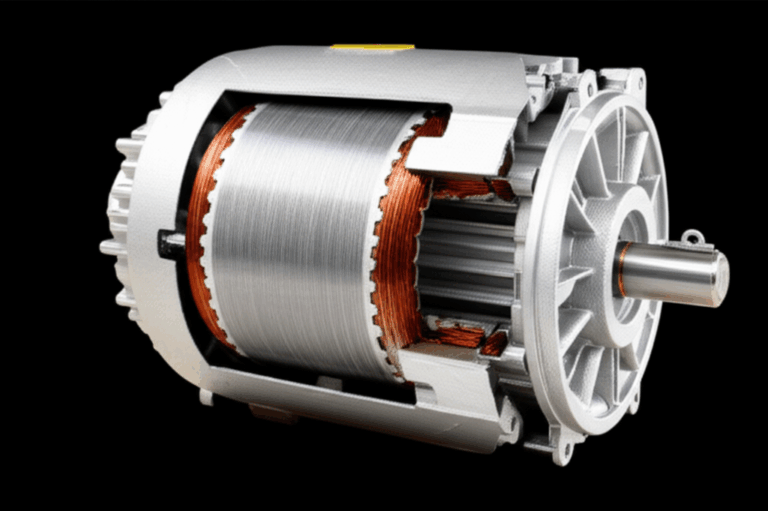
The stator is the stationary part of an electrical machine. It provides mechanical support and a magnetic path. It often houses windings. Those windings might be field windings to create the magnetic field or they might be armature windings where EMF is induced and current flows. The stator never moves.
Functions Across Different Machines
- DC machines: The stator holds the field winding and pole pieces. It creates the stationary magnetic field that the rotating armature pushes against.
- AC alternators and synchronous machines: The stator usually holds the armature winding. The rotating field couples into these windings and induces AC voltage.
- Induction motors: The stator holds the three-phase armature windings that create a rotating magnetic field. That field induces rotor currents and produces torque.
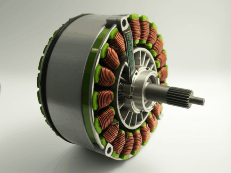
- BLDC motors: The stator holds the armature windings that are electronically commutated. The rotor holds permanent magnets that supply the field.
In each case the stator plays host either to the field or to the armature. It also keeps the machine iron stiff and aligned which matters for the air gap.
What It’s Made Of and Why
- Frame and housing: Provide structure and protect the windings. Often cast iron, steel, or aluminum.
- Laminated core: Stator teeth and yoke are built from thin laminations of silicon steel to cut eddy current loss. The geometry shapes the magnetic circuit, sets the air gap, and controls flux paths.
- Windings: Copper conductors with slot insulation, wedges, and varnish. Good insulation and tight packing improve reliability and heat transfer.
I have pulled apart failed motors where the stator slots showed insulation breakdown due to heat and vibration. Good impregnation and solid slot wedges keep the winding locked in place.
Common Examples You’ll Recognize
- The outer stationary shell of an AC induction motor. That is the stator with its three-phase winding.
- The ring of slots inside a generator where you see heavy copper bars or coils. That is the stator armature.
Armature vs. Stator: Key Differences Summarized
- Motion: The stator is always stationary. The armature can be stationary or rotating depending on the machine type.
- Primary function: The armature does the power conversion. It either generates EMF or carries the main load current for torque. The stator provides a stationary magnetic structure and it houses either the field winding or the armature winding.
- Electrical role: The armature carries the working current. The stator carries field current in DC machines or it carries armature current in AC machines when the armature sits in the stator.
- Naming convention: Armature is a functional name. Stator is a physical name.
Once I started labeling by function, not by location, the fog lifted.
The Interplay: How Armature and Stator Work Together
Electromagnetic induction needs relative motion between a magnetic field and a conductor. You can achieve that by spinning a conductor in a magnetic field or by spinning the field around a stationary conductor. Either way works. The armature and stator make that dance possible.
- The stator provides part of the magnetic circuit. It either carries the field winding or hosts the armature winding.
- The armature interacts with the field. It sees changing flux and picks up EMF or it carries current and produces torque.
- The air gap between stator and rotor is small. That boosts flux linkage and reduces reluctance which improves efficiency.
Faraday’s Law gives the voltage story. Lenz’s Law explains the direction of induced current and why motors develop torque that opposes the change in flux. In practical terms this means the machine resists sudden changes and converts energy cleanly when the magnetic circuit is well designed.
When an Armature Is Part of the Stator (and Vice Versa)
This point tripped me up in my first power machines class. I had learned that the armature rotates and the stator is stationary. That is not always true.
- In DC motors and DC generators, the armature is on the rotor. The stator carries the field winding.
- In AC alternators and most synchronous generators, the armature winding is in the stator. The rotor carries the field winding and uses slip rings or a brushless exciter.
- In induction motors, the main power winding sits in the stator. Many people treat that as the armature. The rotor picks up induced current either in a squirrel cage or in a wound rotor through slip rings.
- In BLDC motors, the armature winding sits in the stator. The rotor carries permanent magnets and acts as the field.
So armature describes the function where EMF is induced or where load current flows. Stator describes the stationary frame and magnetic path. They intersect often. They are not synonyms.
Types of Electrical Machines and Their Armature/Stator Configurations
DC Motors and Generators
- Configuration: Armature on the rotor. Field winding on the stator.
- Key parts: Commutator, brushes, armature winding, field poles.
- How it works: The armature conductors cut the magnetic field and pick up EMF in generator mode. The commutator rectifies that to DC. In motor mode the armature current and the field interact to produce torque.
- Notes: DC machines show copper losses in the armature and field. They also show iron losses in the armature core. Commutator maintenance matters. Brush wear and commutation quality set reliability.
AC Induction Motors
- Configuration: Armature winding in the stator. Rotor with either a squirrel cage or wound rotor.
- Key parts: Three-phase stator winding, laminated stator core, squirrel cage rotor bars and end rings or slip rings and brushes for wound rotors.
- How it works: The stator winding creates a rotating magnetic field. The rotor sees changing flux which induces EMF and current in the rotor. That current and the rotating field develop torque. Slip appears as the difference between synchronous speed and rotor speed.
- Notes: Stator windings carry the main load current. Rotor currents are induced. Good stator design and tight air gap improve efficiency and torque density.
Synchronous Generators and Alternators
- Configuration: Armature winding in the stator. Field winding on the rotor.
- Key parts: Stator armature coils, laminated stator core, rotor with field poles, slip rings and brushes or a brushless exciter.
- How it works: The rotor field rotates and cuts the stator conductors. That induces AC EMF according to Faraday’s Law. Frequency depends on mechanical speed and pole count.
- Notes: Power plants love this layout because you can bring big currents out of a stationary armature without brushes. Cooling and insulation of the stator become critical. Voltage regulation uses excitation control.
Brushless DC (BLDC) Motors
- Configuration: Armature winding in the stator. Rotor with permanent magnets.
- Key parts: Stator armature windings, PM rotor, electronic commutation using a controller and sensors.
- How it works: The controller energizes stator phases to create a rotating field. The PM rotor follows the field and produces torque. No brushes or commutator.
- Notes: Common in electric vehicles, drones, and fans. High efficiency and low maintenance. Torque ripple and control strategy matter.
Across all these machines, you will see the same core ideas repeat. Magnetic field, flux linkage, induced EMF, and torque production. The armature is where the action is. The stator holds the scene steady.
Materials, Losses, and Design Details That Matter
I used to think “iron is iron.” Then I watched a motor run hot at partial load because of iron losses. Materials and geometry matter more than most people expect.
Laminations, Eddy Currents, and Hysteresis
Eddy currents form when changing magnetic fields induce circulating currents in solid steel. Those currents waste power as heat. Hysteresis adds another chunk of iron loss because magnetizing the core takes energy each cycle. We minimize both by building cores from thin electrical steels with insulation between sheets.
- Stators and rotors use stacked lamination sheets. Better steel and thinner laminations reduce iron losses.
- Silicon steel raises resistivity and lowers hysteresis. That is why you will see specifications like M19 or CRNGO for different grades and orientations.
If you want a quick look at how these parts come together, check out these resources:
- The role of stator core lamination in controlling iron losses and shaping flux paths.
- How a well made rotor core lamination improves torque and reduces heat in induction and synchronous machines.
- A broader overview of motor core laminations and where they fit in different machine types.
- Materials matter. Dive into the basics of electrical steel laminations to see why silicon steel dominates motor and generator cores.
- For BLDC designs, the geometry of a good bldc stator core affects cogging torque, noise, and efficiency.
I have seen motors where cheaper laminations saved a few dollars up front and cost thousands in wasted energy over the life of the machine. Buy good steel. Stack it well.
Air Gap, Permeability, and Reluctance
The magnetic circuit runs through the stator teeth, across the air gap, into the rotor, and back. The air gap has low permeability compared to steel. That means it dominates magnetic reluctance. Smaller air gaps increase flux and torque. Too small and you risk rotor-stator rub due to thermal growth or bearing wear.
- Permeability: How easily a material carries magnetic flux. Steel has high permeability. Air has low permeability.
- Reluctance: The magnetic version of resistance. The air gap adds big reluctance.
I set air gaps with care. A few thousandths of an inch can change torque and noise. It also changes inrush current and the shape of the magnetic field.
Windings, Copper Losses, and Insulation
Copper losses (I²R) scale with current. Armature windings carry heavy current in both motors and generators. That makes conductor size, slot fill, and cooling critical. The stator might carry field current in DC machines or the main armature current in AC machines.
- Use good insulation systems and impregnation. Heat, vibration, and contamination break down insulation fast.
- Pay attention to slot geometry. High slot fill is great until it traps heat.
- Watch for circulating currents in parallel paths. They add loss and hot spots.
I once cured a recurring stator failure by switching to a better varnish and improving the bake cycle. Nothing else changed. The winding stayed cool and tight and the failures stopped.
Rotors, Bearings, and Cooling
The armature on a rotor brings mechanical parts into play. Bearings set alignment and control the air gap. Cooling moves heat out of the stator and rotor.
- Bearings and shaft alignment keep the rotor centered. That protects the air gap and reduces vibration.
- Cooling may be natural convection, forced air, or liquid. Stator windings and cores need open paths for air and good thermal contact with the frame.
- Housing and frame should be sturdy. A stiff stator reduces vibration and noise.
I check end play and bearing condition before I blame the windings for heat or noise. Mechanical health affects electrical performance more than most people think.
Practical Analogies and “Aha” Moments
Here is the analogy that helped me. Picture a guitar. The strings vibrate and create sound. The guitar body shapes and amplifies that sound. In many machines the rotor acts like the moving string and the stator acts like the body. Swap roles for an alternator where the “string” is the rotating field and the “pickup coil” sits on the stator. Different arrangements same song.
Another analogy. Think of a bicycle dynamo. Spin the wheel and the magnet rotates past stationary windings. That induces EMF in the stator armature. If you took those windings and spun them in a stationary magnetic field you would still generate power. Either the conductor moves or the field moves. Faraday does not care.
These pictures cut through the jargon. Armature equals the power-conversion conductor set. Stator equals the stationary magnetic structure and support.
Maintenance Tips and Troubleshooting Pointers
I learned these the hard way with a few burned windings and some loud bearings.
- Start with basics. Inspect the air gap for rub marks. Check bearings and shaft end play. Mechanical issues masquerade as electrical faults.
- Measure winding resistance phase to phase. Look for imbalance. High resistance hints at bad joints. Low resistance suggests shorted turns.
- Insulation tests matter. A megohmmeter can save you from re-energizing a near failure.
- Watch for hot spots with an infrared camera. Stator teeth and end windings show problems early.
- In DC machines, check brush wear and commutator condition. Poor commutation causes sparking and heat. That cooks the armature.
- In induction motors, check current balance on the three phases. Unbalance heats the stator and reduces torque.
- Keep things clean. Dust and oil increase temperature and degrade insulation.
Most “mystery” problems trace back to heat, contamination, or mechanical misalignment. Fix those and the armature and stator will thank you with long life.
Conclusion: Focus on Function First
So are the armature and stator the same? No. The stator is the stationary frame and magnetic path. The armature is the functional part where EMF is induced or where working current flows to produce torque. Sometimes the armature sits inside the stator as in alternators, induction motors, and BLDC motors. Sometimes it spins as the rotor as in DC machines.
Once you treat armature as a function and stator as a place, the tangle disappears. You can walk up to any motor or generator and map the roles in minutes. Look for where the main current flows. Look for where the magnetic field lives. Trace the flux path across the air gap. The machine will tell you which part is which.
Frequently Asked Questions (FAQs)
Q: Is rotor the same as armature?
A: Not always. In DC motors and DC generators the armature is on the rotor. In many AC machines the armature sits in the stator. Rotor describes the rotating part. Armature describes the power-conversion function.
Q: Is stator the same as field winding?
A: No. The stator is the stationary structure. It can hold a field winding in DC machines or it can hold the armature winding in AC alternators and induction motors. Field winding creates the magnetic field. Armature winding carries the working current or hosts the induced EMF.
Q: Can an armature be stationary?
A: Yes. In alternators, synchronous machines, induction motors, and BLDC motors the armature winding is typically in the stator which is stationary.
Q: What is the main function of a stator?
A: The stator provides a stationary magnetic structure and mechanical support. It houses either the field winding or the armature winding. It keeps the air gap aligned and helps dissipate heat.
Q: Why are armatures and stators important?
A: They sit at the heart of electromechanical energy conversion. The armature is where EMF is induced and where load current flows. The stator frames the machine and shapes the magnetic field. You need both working together to convert electrical power to mechanical power or vice versa.
Q: What materials do armatures and stators use?
A: Laminated silicon steel for cores to reduce eddy currents and hysteresis. Copper for windings. Solid steel or cast housings for structure. Good insulation and often varnish or resin for winding protection.
Q: How do losses differ between armature and stator?
A: The armature typically carries the working current so copper losses are significant. Both armature and stator see iron losses in their laminated cores. Field windings carry smaller currents but still add copper losses.
Q: What role do commutators and slip rings play?
A: Commutators appear in DC machines to switch armature current and maintain torque in one direction. Slip rings deliver excitation current to a rotating field winding in AC machines like alternators and synchronous motors.
Q: Does the number of poles affect the armature-stator relationship?
A: Pole count affects speed and frequency. It sets the synchronous speed in AC machines. It does not change the functional difference between armature and stator. It changes how the flux links with the armature winding and how many slots and coils you need.
Q: How do EV motors and wind turbines fit into this?
A: Most EV motors use permanent magnet synchronous or induction designs. The armature winding sits in the stator in both cases. Wind turbine generators often use synchronous alternators where the stator holds the armature and the rotor carries the field or permanent magnets.
If you keep one simple rule in mind you will stay on track. Armature equals function. Stator equals place. Everything else falls into line around that.

