A Practical Guide to Designing Motor Cores for Automated Winding
You’ve done it. You designed the perfect electric motor on your computer. It’s powerful and efficient. But then, the factory calls. The automated winding machines are jamming. Wires are getting scraped. The production line is slow and you’re throwing away too many failed motors. This is a common and costly problem.
The good news is that the fix isn’t a fancier robot. The secret is a smarter motor core design. By thinking about how a robot will build your motor from the very start, you can save a ton of time and money. This guide will show you how to design a motor core that is easy to build, leading to better quality and faster production.
Table of Contents
- Why Is Designing for Robots So Important Anyway?
- What Are the Four Big Areas to Focus On?
- How Should I Design the Stator Stack?
- Why is Slot Shape the Most Important Thing?
- How Can I Make an Insulation System Robots Love?
- What About Connecting the Wires?
- What Common Problems Can I Design Away?
- How Do I Stop Wires From Snagging and Scraping?
- Why Isn’t My Slot Filling Up Evenly?
- How Can I Protect the Motor’s Insulation?
- How Do I Tame Those Wild End Wires?
- Conclusion: What Are the Key Things to Remember?
- FAQ: Your Questions Answered
Why Is Designing for Robots So Important Anyway?
You might wonder why you should change your design for a machine. Well, it’s a game-changer for a few big reasons. First, it saves a lot of money. Automated winding is super fast. A machine can wind a motor in a fraction of the time it takes a person. This cost reduction in motor manufacturing is huge. Faster work means you can make more motors and sell them for less.
Second, it makes better motors. Robots do the same thing perfectly every single time. This means every motor has the exact same quality. You don’t have to worry about human mistakes. This leads to higher winding precision and better motor-to-motor performance. Think about EV motor manufacturing, where companies like Tesla, Inc. and General Motors need millions of identical, high-quality motors. They rely on robotic motor assembly.
Finally, it can actually make your motor more powerful. Some of the best winding designs, like hairpin winding, are almost impossible to do by hand. Automated machines make these complex patterns possible. This lets you pack more copper into the motor, which is called a higher slot fill factor. More copper means more power and a more compact motor design.
What Are the Four Big Areas to Focus On?
Making a motor core that is automation-friendly isn’t magic. You just need to pay close attention to four key areas of the stator. If you get these right, you’ll be in great shape.
We will look at each of these in more detail.
How Should I Design the Stator Stack?
The stator is made of many thin metal sheets, or laminations, stacked together. Think of it like a deck of cards. Getting this stack right is the first step.
First, you need to choose the right material. Most motors use electrical steel laminations, which come in different electrical steel grades. But for some special motors with complex magnetic fields, a material called Soft Magnetic Composites (SMC) can be a good choice.
Next, how do you hold all those thin sheets together? A loose stack is a disaster for an automated winding machine. The tool can catch on a loose sheet and break. You have a few good options. You can use interlocking laminations, which are stamped with little bumps and holes that snap together. You can also use laser welding or TIG welding to fuse the outside of the stack. A really great method is using Backlack or self-bonding laminations. These sheets come with a thin layer of glue that melts and bonds the stack together when baked.
Finally, you must get rid of sharp edges. The stamping process that creates laminations often leaves tiny, sharp bits of metal called burrs. These burrs are like tiny knives. When the winding machine pulls the wire over them at high speed, they can scrape off the wire’s thin insulation coating. This can cause a short and ruin the motor. You must have a process to remove these burrs, like tumbling the parts in a big drum. A smooth stator core lamination is a happy lamination.
Why is Slot Shape the Most Important Thing?
If there is one thing you must get right, it’s the shape of the slots where the wire is wound. This is called the stator slot design for automation.
The first thing to look at is the slot opening. This is the doorway that the winding tool and wire must pass through. If the opening is too narrow, the tool can’t get in, or it will scrape the wire. But if the opening is too wide, it can hurt the motor’s magnetic performance. It’s a balance. For a needle winding machine, the opening should be wide enough for the needle to pass through with room to spare. A good rule is to have clearance for the winding nozzle.
Next is the shape of the slot itself. You can have slots with straight, parallel sides or tapered slots that get slightly wider at the bottom. Tapered slots can help the wires lay down more neatly, which improves your copper fill factor. This means you get more wire in the same amount of space.
You also need to think about the tooth tip design. The “teeth” are the metal parts between the slots. The tips of these teeth should be rounded or have a little slope. This helps guide the wire smoothly into the slot and prevents it from snagging. A sharp corner here is just as bad as a burr. Small details like the slot corner radius make a huge difference.
Achieving a high fill factor calculation is a key goal. With good design for automation, a needle winding technology process can achieve a 45-55% fill factor. Advanced methods like hairpin winding can go even higher, sometimes over 60%! It’s a trade-off between motor performance vs. manufacturability.
How Can I Make an Insulation System Robots Love?
The copper wires in a motor can’t touch the steel core. If they do, the motor will short out. We use an insulation system to prevent this. But this system has to be designed so a robot can install it easily.
One common method is using slot liner insulation. This is a special paper or film, like Nomex or Mylar, that gets folded and pushed into each slot. For automation, you should design these liners with “cuffs,” or folded-over edges. Cuffs make the liner stronger and easier for a machine to grab and insert. Automated insulation insertion is much faster and more consistent than doing it by hand.
An even better way is to use injection-molded plastic parts. You can design plastic end caps that snap onto each end of the stator core. These parts can have the slot insulation built right in. They can also have special channels and guides for the wire, which makes the winding process even smoother. This is a key part of Design for Manufacturing (DFM) for motors.
Another high-tech option is epoxy powder coating for stators. Here, the whole stator is heated up and coated in a special plastic powder. The powder melts and forms a smooth, tough layer of insulation over the entire part, even inside the slots. This gives amazing insulation protection and is perfect for high-voltage motors, like a BLDC motor core.
What About Connecting the Wires?
After the main body of the motor is wound, you still have to connect the ends of the wires. This is called termination. Doing this by hand is slow and a common place for mistakes. A production-friendly motor design thinks about this from the start.
A great idea is to design the plastic end caps we talked about earlier to include terminal connection design. You can have pins or blades molded right into the plastic. The winding machine can then be programmed to automatically wrap the wire ends around these pins. Then, another automated process can weld or crimp them.
You also need to think about lead wire management. The design should give the robots plenty of room to work. There needs to be enough clearance for tools to strip the wire ends and make the final connection. By planning for automated lead termination, you can remove a big bottleneck in your motor assembly automation process.
What Common Problems Can I Design Away?
Many of the biggest headaches on the production line are not manufacturing problems. They are design problems. By thinking ahead, you can design these problems right out of your motor. Let’s look at a few common ones.
| Design Parameter | Common Challenge | Best Practice / Solution |
|---|---|---|
| Slot Opening | Too small for the winding tool; scrapes wires. | Make the opening wide enough for the tool. Add a gentle slope on the tooth tips to guide the wire in. |
| Lamination Edges | Sharp burrs cut the wire’s insulation. | Add a step to your process to remove burrs. Set a rule for how smooth the edges must be. |
| Insulation System | Inserting paper liners by hand is slow and sloppy. | Use plastic end caps with built-in insulation. Design paper liners that are easy for a machine to handle. |
| End-Turn Geometry | The loops of wire at the end are messy and too big. | Design the plastic end caps with channels that guide and shape the end wires neatly. |
How Do I Stop Wires From Snagging and Scraping?
This is maybe the number one enemy of automated winding. A tiny scrape on the wire can be invisible, but it can cause the whole motor to fail.
The solution is simple: make everything smooth. Imagine you are the wire. You are being pulled at high speed through the motor. Any sharp edge is a danger.
- Solution: Make sure all corners in the slot have a generous radius. A radius of at least 0.2mm is a good start. The tooth tip geometry should be rounded or chamfered. And as we said before, you absolutely must have burr-free laminations. This simple step can reduce motor failures from shorts by over 90%. It makes your general motor core laminations much more reliable.
Why Isn’t My Slot Filling Up Evenly?
You designed the motor for a 50% slot fill, but the factory can only get 40%. This is a common problem. It leads to lower power and a motor that gets too hot.
Often, the problem is that the stator stack isn’t consistent. If the stator pack height tolerance is loose, some stators will be shorter or taller than others. This changes the slot volume and messes up the winding machine’s careful plan.
- Solution: You need tight control over your lamination and stacking process. Using precise methods like welding or Backlack helps a lot. You also need to work with the automation team to create an optimized winding pattern. The machine needs to know exactly how to lay the wires to pack them in tightly and neatly, like in an orthocyclic winding pattern.
How Can I Protect the Motor’s Insulation?
Sometimes, the insulation itself gets damaged as it’s being put into the stator. The sharp corners of the slot can tear the paper liner.
This is another problem that comes down to a smart slot opening geometry.
- Solution: A slightly tapered or “funnel” shape at the top of the slot opening can help guide the insulation paper in without catching or tearing. Using tougher insulation materials, like those with an Insulation Class H rating, can also help. The design of the insertion tool is also important. It should be designed alongside the stator itself.
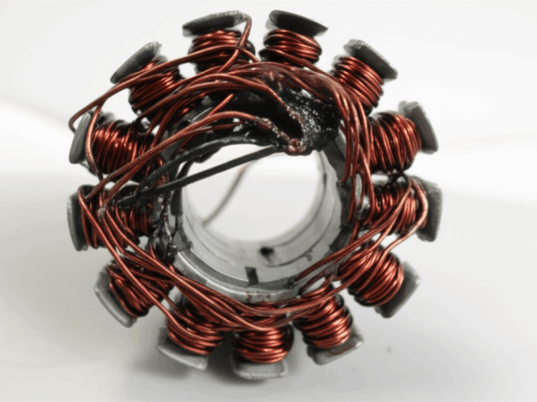
How Do I Tame Those Wild End Wires?
The coils of wire don’t just stay inside the slots. They have to loop around the ends of the stator. These loops are called end turns or the winding overhang. If they are messy and uncontrolled, they can get too big. This wastes copper, makes the motor less efficient, and can make it hard to fit the motor into its housing.
This is a perfect job for those molded plastic end-cap insulators we talked about.
- Solution: You can design channels, walls, and guides directly into the plastic end caps. As the machine winds the wire, these features force the end turns to form a neat, tight, and predictable shape. This helps with minimizing end-winding volume and creating a more powerful and compact motor design.
Conclusion: What Are the Key Things to Remember?
Designing a motor for automated winding isn’t about giving up performance. It’s about designing smarter so you can get both great performance and great manufacturability. It requires teamwork between the motor designers and the manufacturing engineers.
- Smooth is Fast: Get rid of all sharp edges and burrs on your laminations. Make slot corners and tooth tips rounded.
- Open the Door: Make sure your slot opening is wide enough for the winding tool to get in and out easily without touching the sides.
- Integrate and Guide: Use molded plastic parts to combine the insulation, wire guides, and terminal holders into one smart piece.
- Keep it Tight: Use interlocking, welding, or bonding to create a solid, stable stator stack that won’t shift during winding.
- Plan Ahead: Think about every step of the automated process, from stacking the core to connecting the final wire.
FAQ: Your Questions Answered
What is a good slot fill factor for automated winding?
It depends on the method. For standard needle winding, aiming for 45% to 55% is a realistic and good target. For more advanced methods like hairpin winding, you can design to achieve over 60% or even 70%.
How does slot opening width affect manufacturability?
It’s critical. A wider opening makes it much easier and faster for the winding tool to do its job, which reduces cycle time. It also lowers the risk of scraping the wire insulation. However, an opening that is too wide can slightly reduce the motor’s magnetic efficiency. It’s a key tradeoff you need to balance.
What is the difference between designing for needle winding vs. hairpin winding?
For needle winding, you design slots that a long, thin needle can move in and out of. For hairpin winding, the design is very different. You create open slots where you can insert large, pre-formed copper bars that look like hairpins. The design must then allow for those hairpin ends to be automatically twisted and welded together.
Can any stator be automatically wound?
No, not really. While you can try to automate winding on a core not designed for it, you will likely face many problems like low speed, damaged wires, and inconsistent quality. The best results always come from motors that were designed for automation from the very beginning.